# Sprayer Calibration
Calibrating the Sprayer is process where the timing is adjusted for when the Sprayer activates and deactivates. The calibration process uses a dedicated test field which is a route plan stored on the Turf Tank One. If the timing is incorrect for i.e. spray activation, the line painted line will either start to soon or to late. Same applies for spray deactivation.
Important
- For Sprayer Calibration it is recommended to use a flat nozzle.
- Using a round nozzle will produce an inaccurate results according the process described and shown images.
When calibrating the Sprayer you are using a regular plan.
It is therefore important to:
- Ensure that the requirements for placing the Base Station is kept.
Please see Placing The Base Station. - The Satellite Connection Bar must be green.
Please see Dashboard
# Why is it important with a correct calibrated sprayer?
It is important to have correct calibrated sprayer in order to achieve the following examples:
- Good corners at a given field.
- Aligned hash marks (i.e. American football).
# Field corners
Shown below are examples of good and bad field corners.
Please Note
- The good example is an ideal scenario.
- Since the Turf Tank One is working of coordinates small variations is likely to occur.
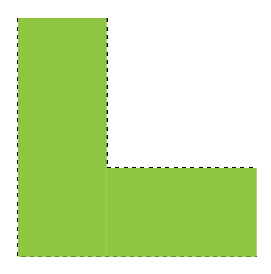
Good (the lines meet at the corner)
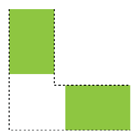
Bad (the lines do not meet)
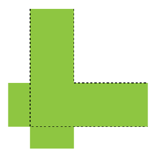
Bad (the lines “overshoot”)
# Hash marks
Shown below are examples of good and bad hash marks.
Please Note
- The good example is an ideal scenario.
- Since the Turf Tank One is working of coordinates small variations is likely to occur.

Good (the hash marks aligns in top and bottom)

Bad (the hash marks do not align in top and bottom)
# How often must the Sprayer be calibrated?
Calibrating the Sprayer is recommended when:
- Changing the nozzle to a different type.
- Changing paint brand.
- The Paint System is thoroughly cleaned.
- Paint tubes are replaced.
- Pump is replaced.
# Does the calibration process require a specific location?
It is not required that the Sprayer is being calibrated next to field which is going to be painted. The calibration can be done anywhere since the calibration values are tied to the Turf Tank One only.
# Does the calibration process require a specific Position Mode?
It is not required that the Sprayer is being calibrated with a specific Position Mode, i.e. Saved Position. Calibration can just as well be done using Single Use even if the actual field is painted with Saved Position or Auto Mode .
# Field For Calibration Routines
The calibration routine has its own dedicated field. The field is located on the Turf Tank One as a route plan. The field is shown below.
| Field for Sprayer Calibration Type 1 |
|---|
 |
| Field for Sprayer Calibration Type 1 | |
|---|---|
| Length | 365cm (12ft) |
| Width | 102cm (3ft 4”) |
| Paint time | Approx. 160 seconds |
# Calibrating With Sprayer Calibration Type 1
Calibration process overview:
- Paint field For Sprayer Calibration Type 1.
- Inspect Cross Lines.
- Select Cross Line scenario.
- Adjust Sprayer Calibration values.
- Repaint field for Sprayer Calibration Type 1 (to check adjusted calibration values).
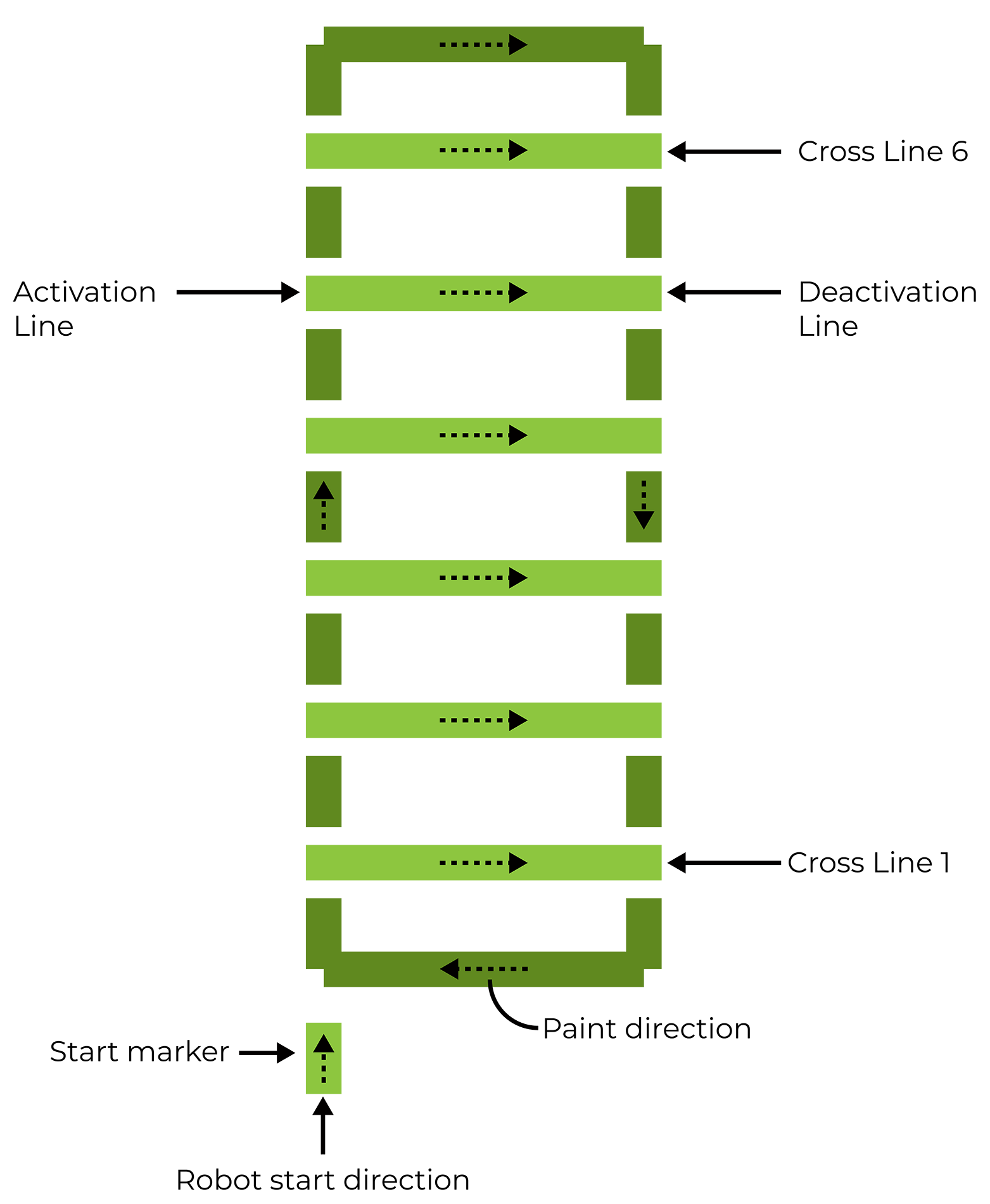
Field for Sprayer Calibration Type 1
Field for Sprayer Calibration Type 1 consists of the following:
- 1 outer rectangle (illustrated below in dark green).
- 6 cross lines (illustrated below in light green).
- 1 start marker (shows in which direction the Robot starts when painting the field).
Please Note
- It is required that the field for Sprayer Calibration Type 1 is painted with a line width of 10cm (4”).
- Adjusting the line width is described here:
Adjusting distance between Spray Discs
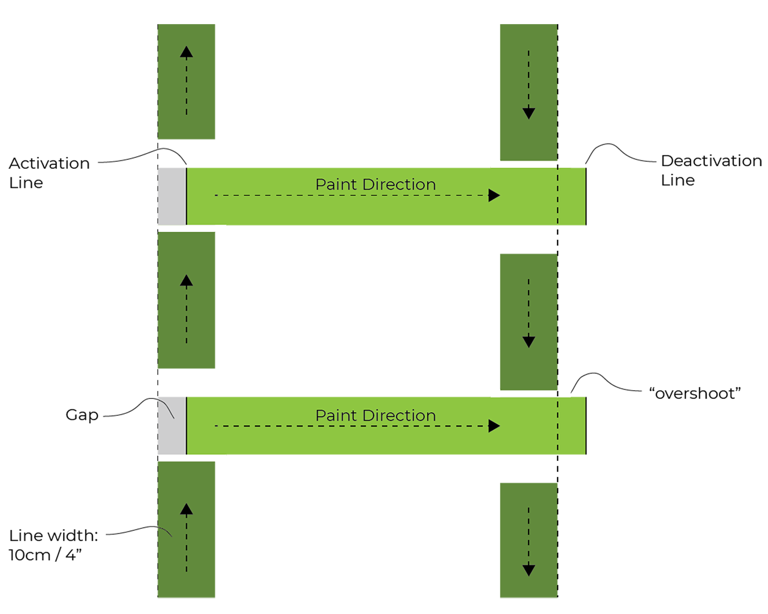
The field shown below illustrates an example of a correct calibration where all activation and deactivation lines align to the outside of the rectangle.
The field shown below illustrates an example of an incorrect calibration where all activation and deactivation lines do not align to the outside of the rectangle. The activation lines are all on the inside of the rectangle, and all deactivates lines are on the outside.
Sprayer Offset
Even with the Activation and Deactivation Lines aligning to the outside of the rectangle, the Cross Line may look like they have shifted up or down. Examples are shown below. If this is the case, it is a likely sign that the Sprayer Offset needs to be adjusted.
Example of where the Cross Lines are shifted up:

Example of where the Cross Lines are shifted down:

# Step 1 - Paint field for Sprayer Calibration Type 1
Please Note
- The following description is using App version 1.4.1.1
- Before painting the field, it is required that the Base Station is turned ON and the Turf Tank One is placed at the location and in the direction where the field is going the painted.
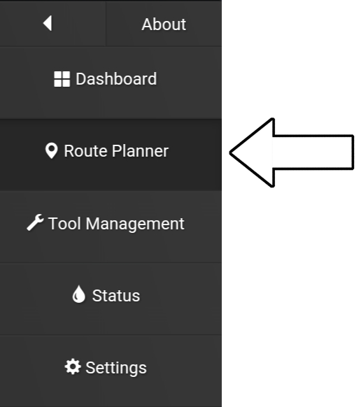
1. Open the App.
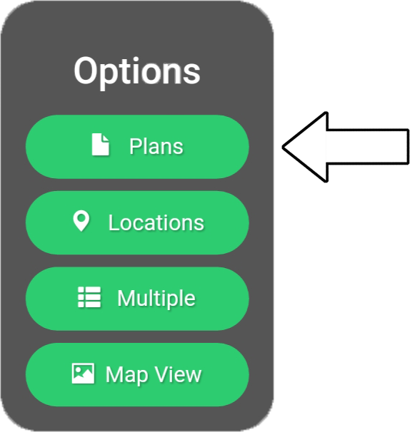
2. Go to “Route planner”.
3. Press “Locations”.
Please Note
- An existing location can also be used.
- If using an existing location then jump to step 8.
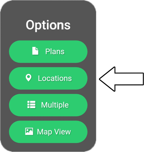
4. Press “New location”.
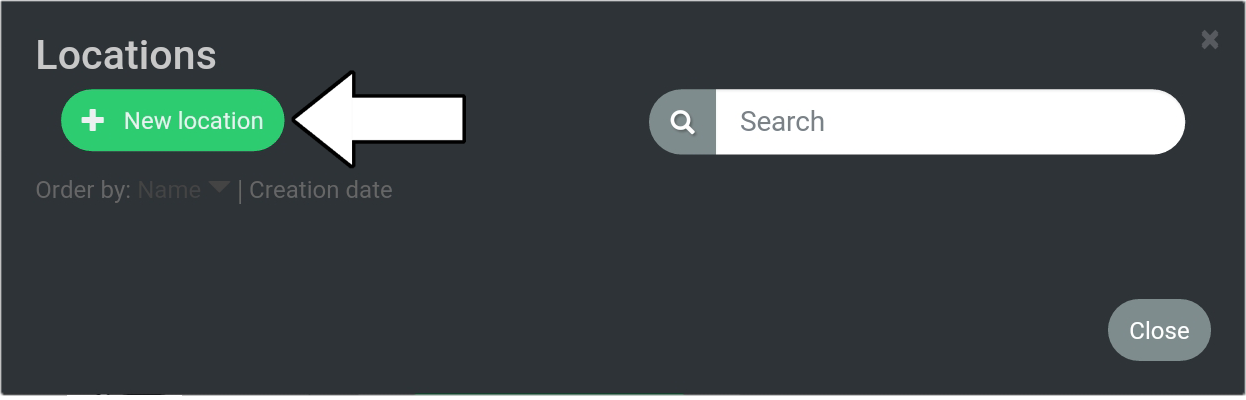
5. Type in name for new location, i.e. Test

6. Press “OK”
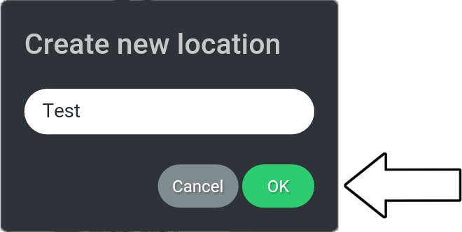
7. Press “Close”
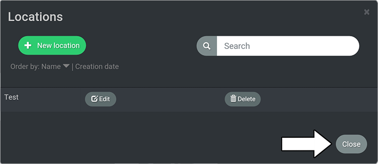
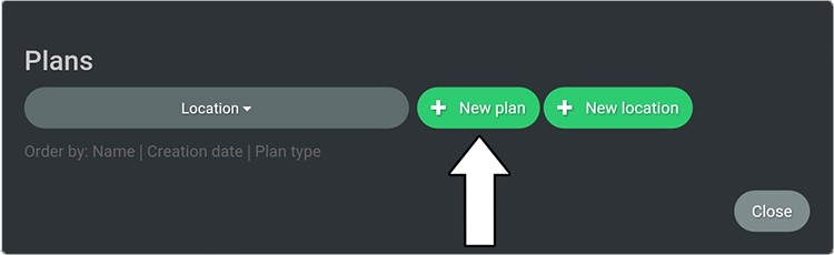
8. Press “Plans”
9. Press “New plan”
10. Press “New field”
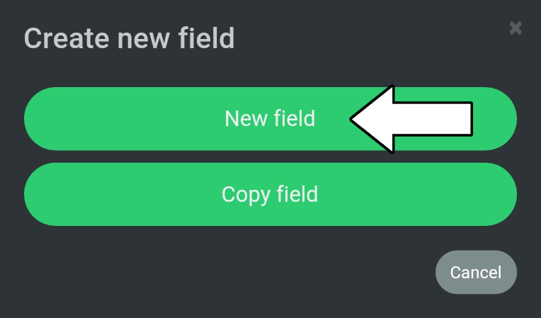
11. Select “Test” from the categories.
12. Select “Sprayer Calibration Type 1”.
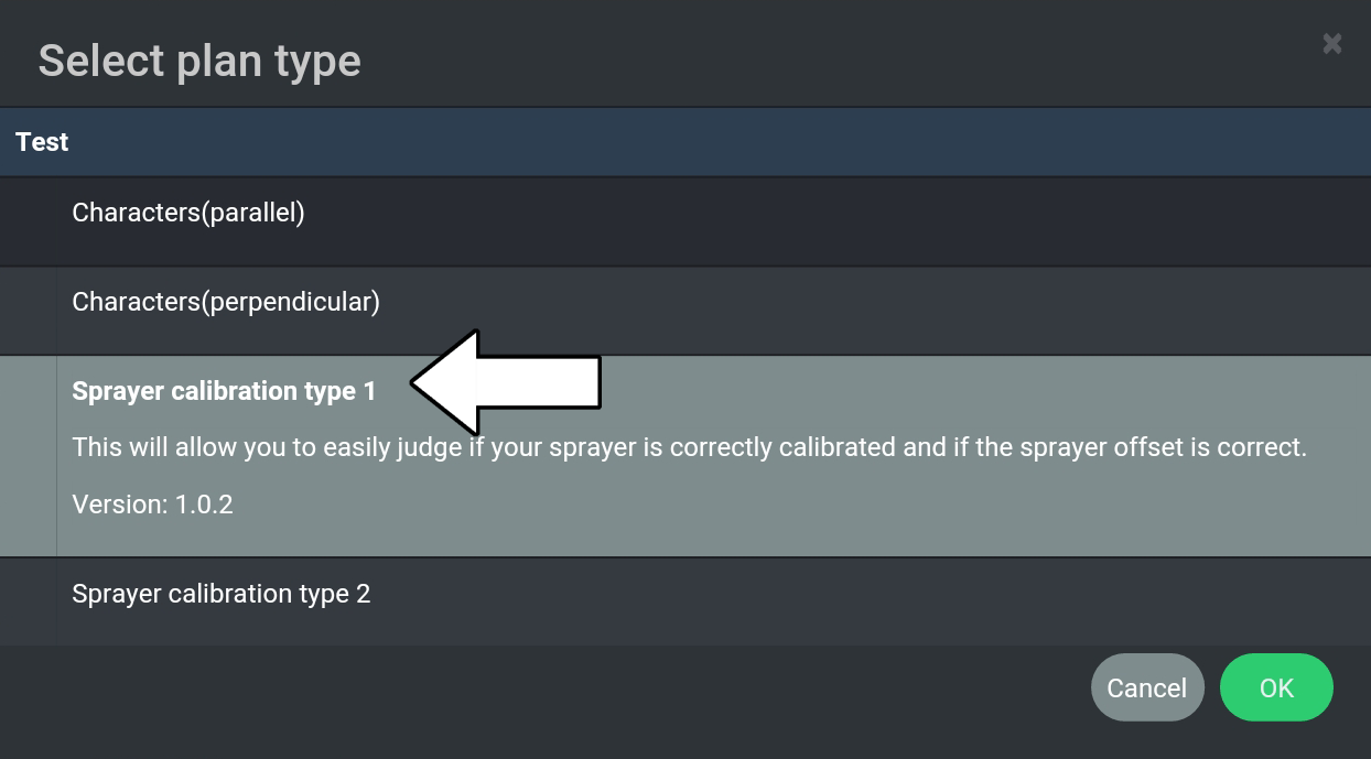
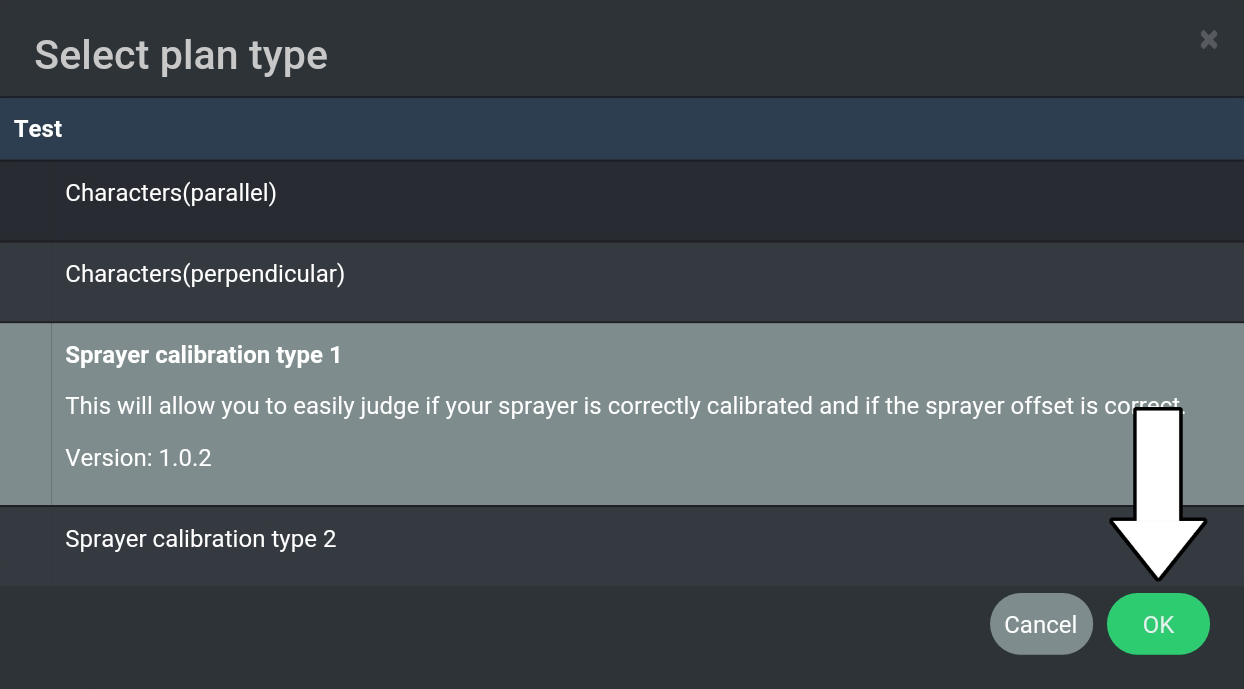
13. Press “OK”
14. Provide a name, i.e. “Type 1”.
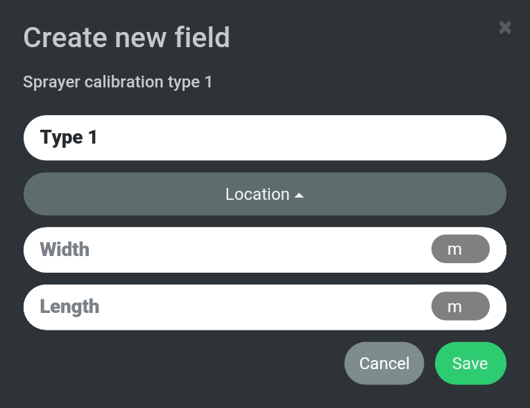
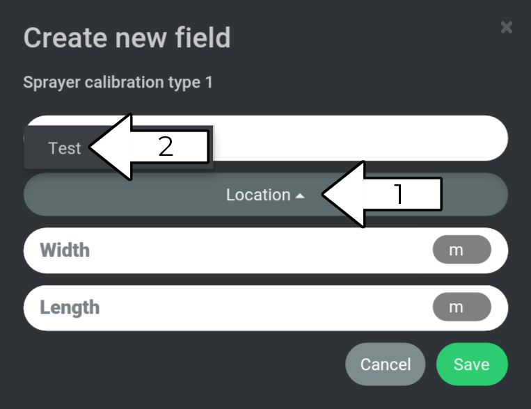
15. Select “Location” (1) and then “Test” (2).
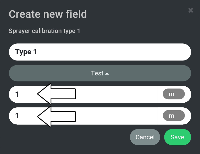
16. Provide a dimension for length and width, i.e. 1 for both.
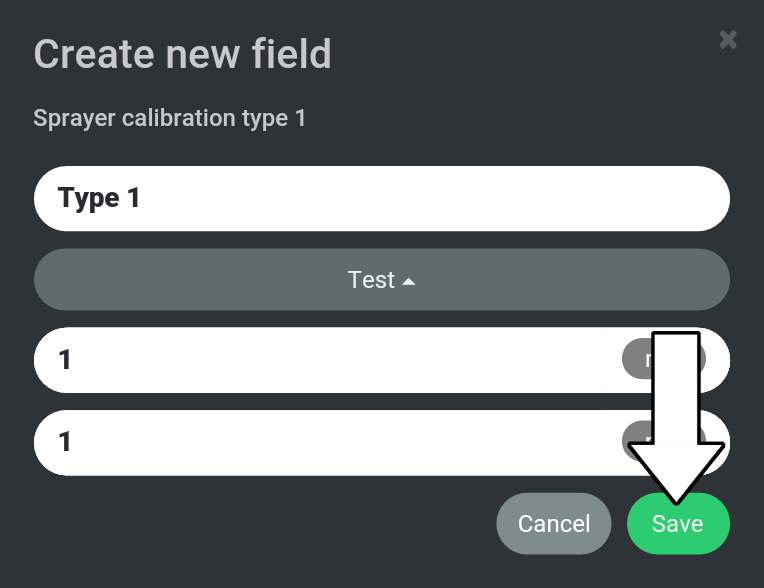
17. Press “Save”.
18. Press “Load”.
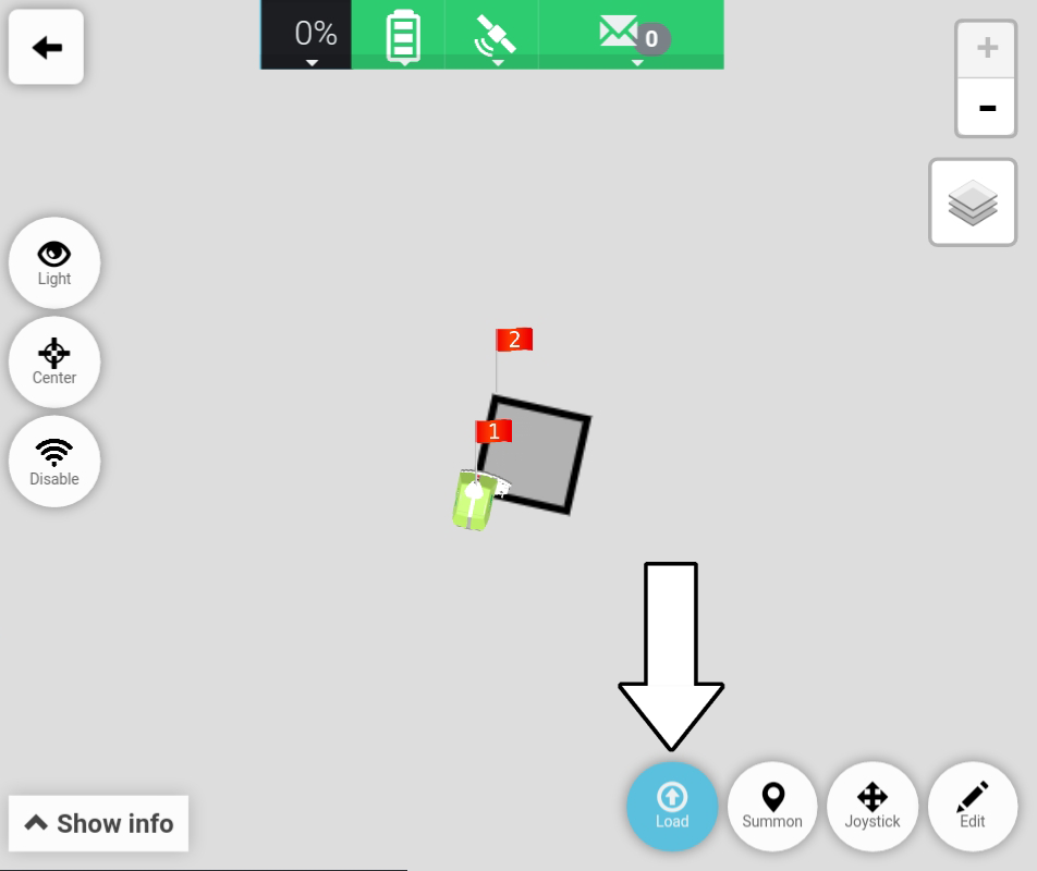
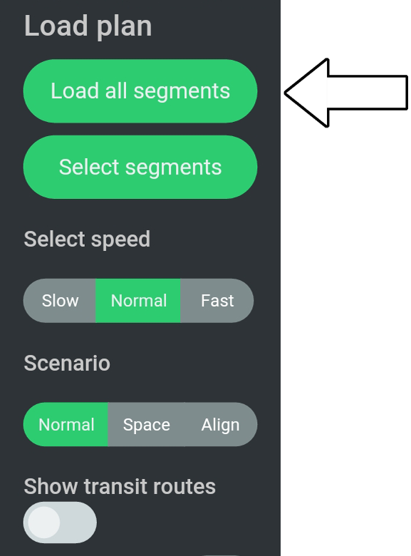
19. Press “Load all segments”.
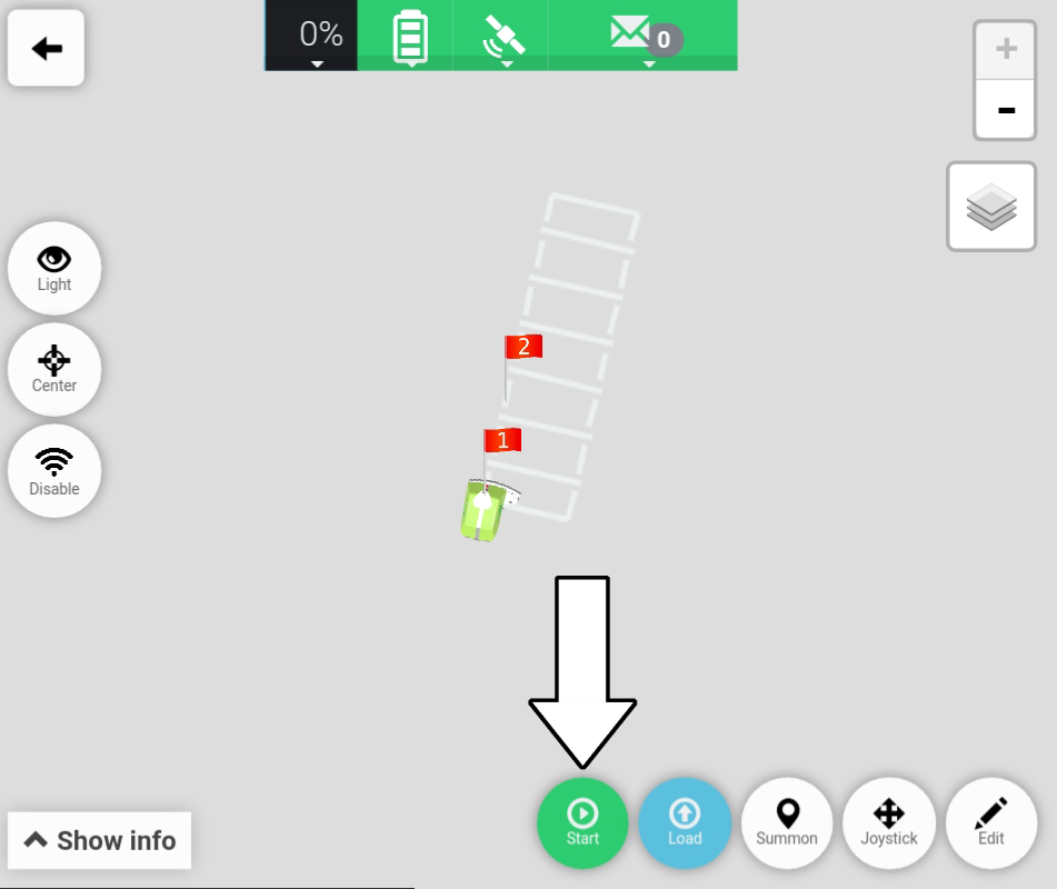
20. Press “Start”.
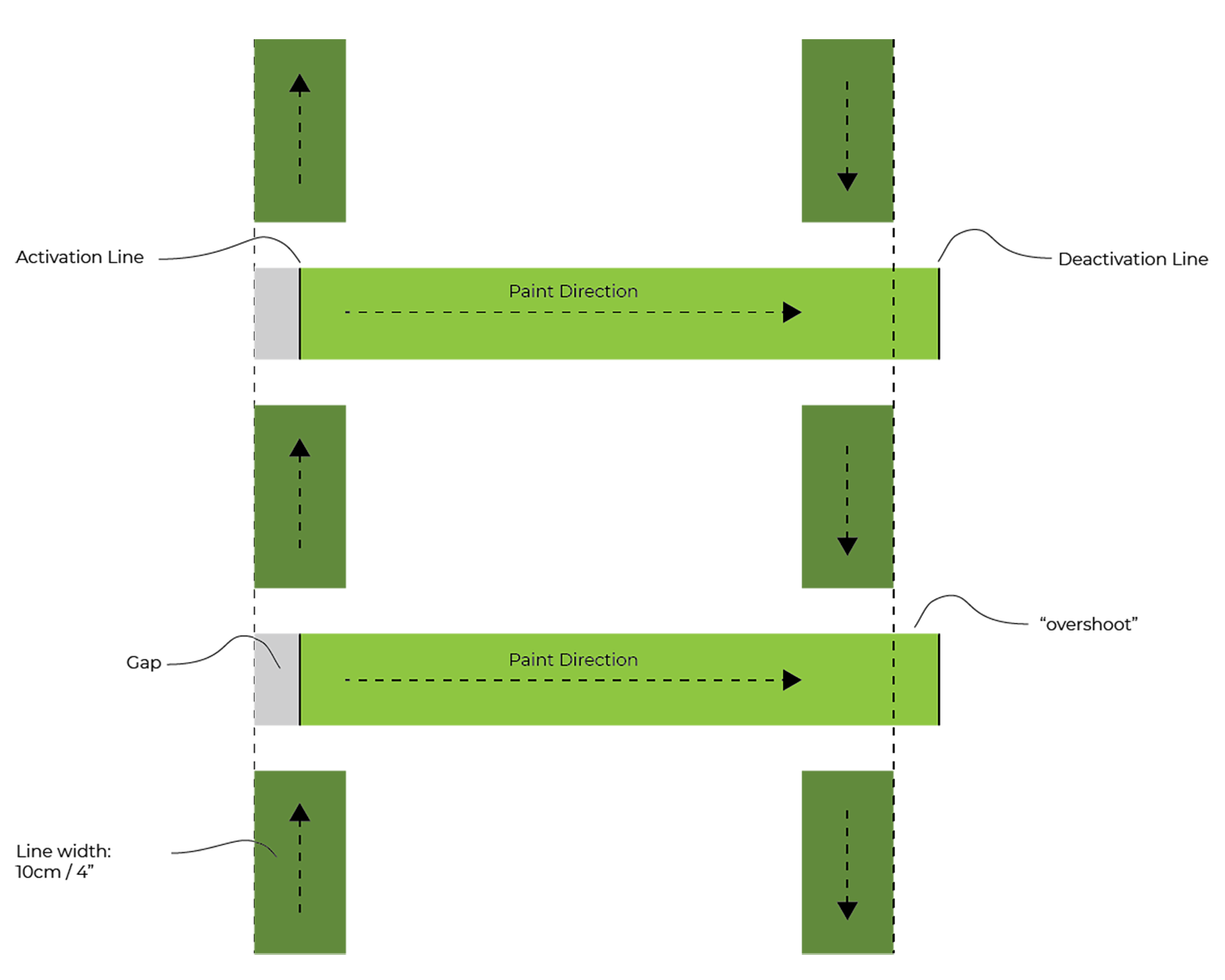
# Step 2 - Inspect Cross Lines
Having painted the field for Sprayer Calibration Type 1, the next step is to inspect all cross lines and check the tendency for Activation and Deactivation lines.
Examples of incorrect calibration
In the example below an incorrect Sprayer calibration is shown where the Activation Line starts on the inside of the rectangle and leaves an open gap. Additionally, the Deactivation Line “overshoots” and stops on the outside of the rectangle.
In the example below an incorrect Sprayer calibration is shown where the Activation Line starts on the outside of the rectangle (starts to soon), and the Deactivation Line stops inside the rectangle and leaves an open gap.

# Step 3 - Select Cross Line scenario
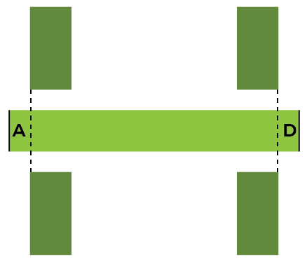
Knowing how the cross lines look, the next step is to select a scenario which best describes the tendency for all six cross lines. The scenarios (1-5) are shown below. For each scenario it is described how Activation and Deactivation must be changed (increased or decreased) and the amount (time per distance).
Please Note
The amount of change (seconds per cm or seconds per inch) may vary from one Turf Tank One to another. However, the values do indicate at what level (seconds) the operator should be looking. It is not changing the value with i.e. 1 second.
Scenario 1
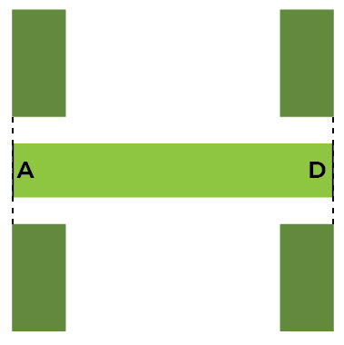
| Description | Change required | Change amount |
|---|---|---|
| Activation Line (A) aligns with outside of rectangle. | Activation value: No change | None |
| Deactivation Line (D) aligns with outside of rectangle. | Deactivation value: No change | None |
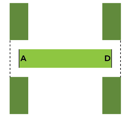
Scenario 2
| Description | Change required | Change amount |
|---|---|---|
| Activation Line (A) starts inside rectangle | Activation value: Needs to be increased. | 0,025s for every 1cm. or 0,03s for every ½”. |
| Deactivation Line (D) stops outside rectangle. | Deactivation value: Needs to be increased. | 0,03s for every 1cm or 0,04s for every ½”. |
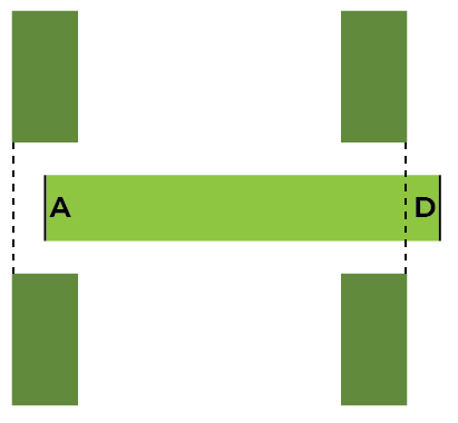
Scenario 3
| Description | Change required | Change amount |
|---|---|---|
| Activation Line (A) starts outside rectangle. | Activation value: Needs to be decreased. | 0,025s for every 1cm. or 0,03s for every ½”. |
| Deactivation Line (D) stops inside rectangle. | Deactivation value: Needs to be decreased. | 0,03s for every 1cm or 0,04s for every ½”. |
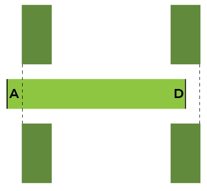
Scenario 4
| Description | Change required | Change amount |
|---|---|---|
| Activation Line (A) starts inside rectangle | Activation value: Needs to be increased. | 0,025s for every 1cm. or 0,03s for every ½”. |
| Deactivation Line (D) stops inside rectangle. | Deactivation value: Needs to be decreased. | 0,03s for every 1cm or 0,04s for every ½”. |
Scenario 5
| Description | Change required | Change amount |
|---|---|---|
| Activation Line (A) starts outside rectangle. | Activation value: Needs to be decreased. | 0,025s for every 1cm. or 0,03s for every ½”. |
| Deactivation Line (D) stops outside rectangle. | Deactivation value: Needs to be increased. | 0,03s for every 1cm or 0,04s for every ½”. |
# Step 4 - Adjust Sprayer Calibration values.
Knowing how much to change the change the Activation and Deactivation value, next step is to change the values.
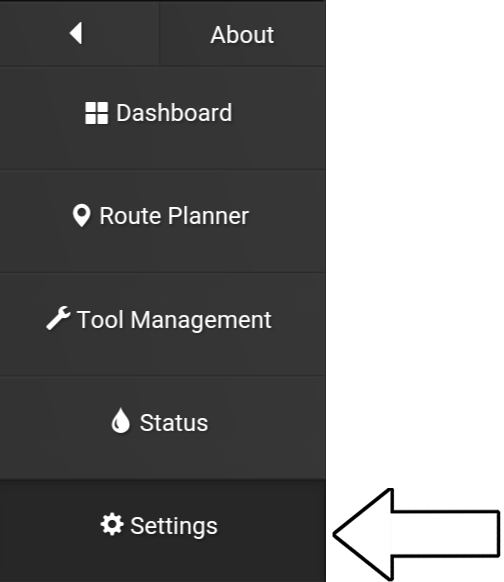
1. Open the App.
2. Go to “Settings”.
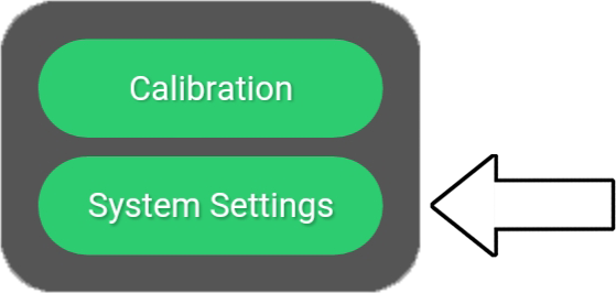
3. Press “System Settings”.
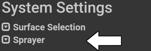
4. Press “Sprayer”.
5. Insert new value for “Activation Delay” and “Deactivation Delay” by pressing on each value.
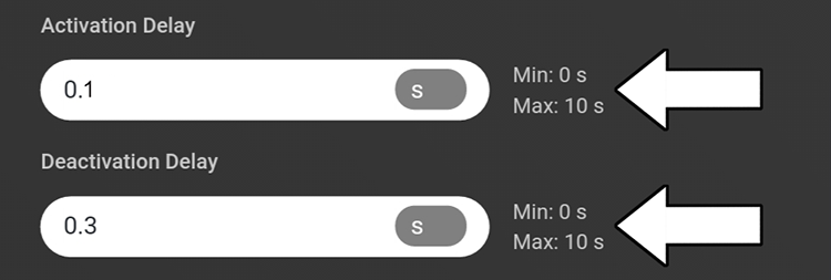
6. Press “Save settings”.

Example
When combining the painted field with the cross lines scenarios, it was found that Activation needed to be decreased by 0,1s.
Currently values is 0,2.
New value is therefore: 0,2 – 0,1 = 0,1.
# Step 5 - Repaint field for Sprayer Calibration Type 1
With the adjusted values it is recommended to repaint the same field to check the effect of the new values.
It is furthermore recommended to create a new field rather than loading the same field already created.
If loading the same field, the field with adjusted values will be positioned on top of the previous.
It can therefore be hard to see the change.
Creating and painting a new field is described here:
Paint field For Sprayer Calibration Type 1.
# Further notes
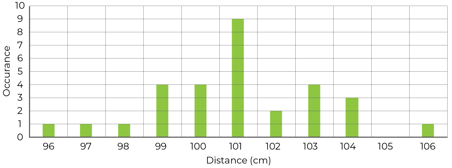
# Line length will vary
When painting hash lines, each line will not necessarily be exactly the same length. The diagram below shows the length variation of 30 lines. Each with a nominal length of 101,6cm. The average length for all 30 lines is 101cm.
# Too high Activation value can result in a "pre-spray"
If the Activation value is too high the Sprayer may produce a "pre-spray" which shows as a triangle followed by a thin line. An example of the pre-spray triangle is shown below.
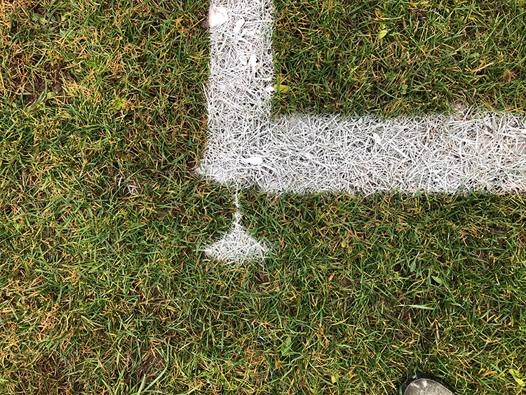
By increasing the Activation value even more, the small line leading away from the triangle increases in length, and the triangle moves further away from the actual field.